About
The electronic die is an 'electronically augmented' playing die. It can be used as a drop-in replacement for regular die, or it can be leveraged in games that straddle the gap between physical and digital games.
Note that work on the second version of the die is well underway, with the next iteration featuring full RGB leds and wireless charging!
I created a project page for the dice on hackaday.io, check there for updates on the development!
Hardware
The dice are based around a Simblee module (that conveniently combines an nRF51 chip with a chip antenna). The LEDs are charlieplexed using an I2C GPIO controller (mostly because the Simblee module cannot source or sink enough current). There is, of course, an accelerometer to detect orientation, and a small EEPROM to store non-volatile data.
There is even a small magnetic switch such that I can eventually build a carrying case with small embedded magnets that will make sure the dice remain off during transport.
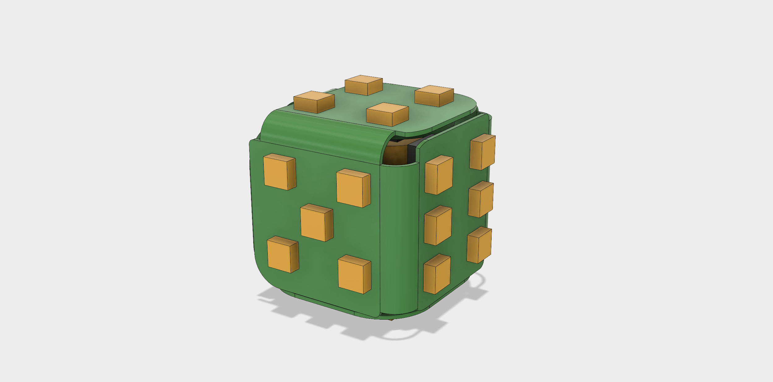
All the electronics are soldered onto a flexible pcb and then wrapped around the battery in a cube shape, so that the LEDs face outward. All the other components had to be on the other side of the board.
The case is 3D printed (Shapeways) and currently measures 17mm on its side (a standard die is 16mm).
The Software Side of Things
A lot of the magic of the Electronic die can only happen with a solid software stack. I like to split the code side of the project in two parts, the firmware, or code that is running on the die itself, and the app, or code that is running on the phone.
Here is the Arduino environment compiling a program for the die. 132k of program data and 32k of ram!
The firmware is written in what I call C+, essentially C++ but without all the fancy container stuff. The hardware is so limited, only about 32k of ram (and that's actually a lot) that it wouldn't make sense to start writing code that requires memory allocators and other nonsense like that.
The microcontroller inside the die is called a Simblee, and it makes a lot of the process very easy. It is compatible with the Arduino environment, meaning that you can just plug your usb adapter to the chip and start downloading your code without having to deal with makefiles, memory layout or command-line programming tools. Stuff just works. On top of that, the folks at RFDigital provide a decent bluetooth LE API, making the whole process that much easier.
The app, on the other hand, is written in C#. As a game developer, I have become quite familiar with the Unity game engine, and in fact have been using it in my other projects a lot. Unity has the great advantage that it runs on many, many platforms, including PC and iOS.
While the app ultimately needs to run on a phone or ipad, during development, it is way, way faster to work dirrectly on desktop.
The typical Unity Development environment.
There was one small problem though, I couldn't find a Bluetooth LOW ENERGY asset for Unity that worked on Windows. For reasons that I won't go into here, while Unity lets you write code in C# and use .NET libraries, it is several versions behind Microsoft official .NET release in terms of functionality/compatibility, and BLE support in Windows (and .NET) is a fairly new thing. Fortunately, Unity also lets you interface with Native dlls (libraries written for good old fashioned Win32), and there IS an API for BLE on Windows in native Win32 C.
Yum... Win32 APIs...
I ended up adapting an existing Unity asset, that had Bluetooth LE support for both iOS and Android, but nothing else, to also support Windows through my own native DLL! Needless to say, Windows API are a nightmare. The native DLL source code can be found <here>, but unfortunately, it won't be a tremendous use without the asset, which I can't give out sources to, as the asset isn't free! I'm hoping maybe the author and I can work out something so that there is a Unity package out there that supports all 3 platforms!
Firmware architecture
With the development environment sorted out, I turned to the firmware itself. As I mentioned, memory is fairly limited on device, so I wanted to strike a balance between good programming practices and simplicity. Most system devices of the micro I used because their own global objects, something I would never do in large-scale software development environments, and I allowed myself to have components talk directly to other components, something else I would also normally forbid as it breaks many principles of good software engineering.
But let's focus on some of the more specific challenges of firmware coding. You can probably imagine: there is no operating system on a microcontroller like this. Your code doesn't have access to threads or file systems, or anything like that. If you want multiple things to happen at once, such as animating LEDs while accessing accelerometer readings and processing bluetooth messages, you need to use the hardware-provided timers and interrupts. Which is exactly what I did.
In fact, the most crucial component of the entire firmware is probably just that, a simple timer component that allows other components (like the LED Animation controller, or Accelerometer Controller) to register for callbacks at specific times, and internally uses the hardware interrupts to make it happen. If you're into low level stuff, the details are quite interesting, as there are several pitfalls awaiting you when you try to coordinate multiple pieces of hardware all relying on the timer and interrupt circuitry at the same time.
In any case, I eventually got something I was happy with, and was able to properly coordinate all the components together, from the LED animations, to the debug console or even the Bluetooth telemetry, a critical piece of code in my quest to optimally determine what state the die is in.
What do I mean? Well I believe that it's super, SUPER important for the die to make as few mistakes as possible in figuring out whether it was thrown or not; to figure out that it's just being handled, being blown on :) or resting on the table! Any mistake means that the player HAS to go fix it on the phone or iPad app, ruining the experience for a bit. And so I need to figure out, from the accelerometer readings, the difference between the different states, and even different kinds of throws. I also want the determination that a roll is 'finished' to be very quick, so that the die can notify the phone and play an animation right away! I don't want it to have to wait a second or two in order to make sure it has stopped moving for instance, that would be lame!
X,Y,Z acceleration and overall magnitude over time.
I've been attempting to graph the data over on the Unity app, and trying to spot easy patterns, but so far nothing brilliant has jumped out at me. I think I need to save the data off to a file, gather a bunch of it, and then run simulations of detection ideas to see what works. What does square magnitude of the acceleration tell me? what about some sort of low-pass filtered data, does it tell me anything about whether the die is spinning somewhat regularly? What does shaking it in your hand look like?
Version 2 Hardware
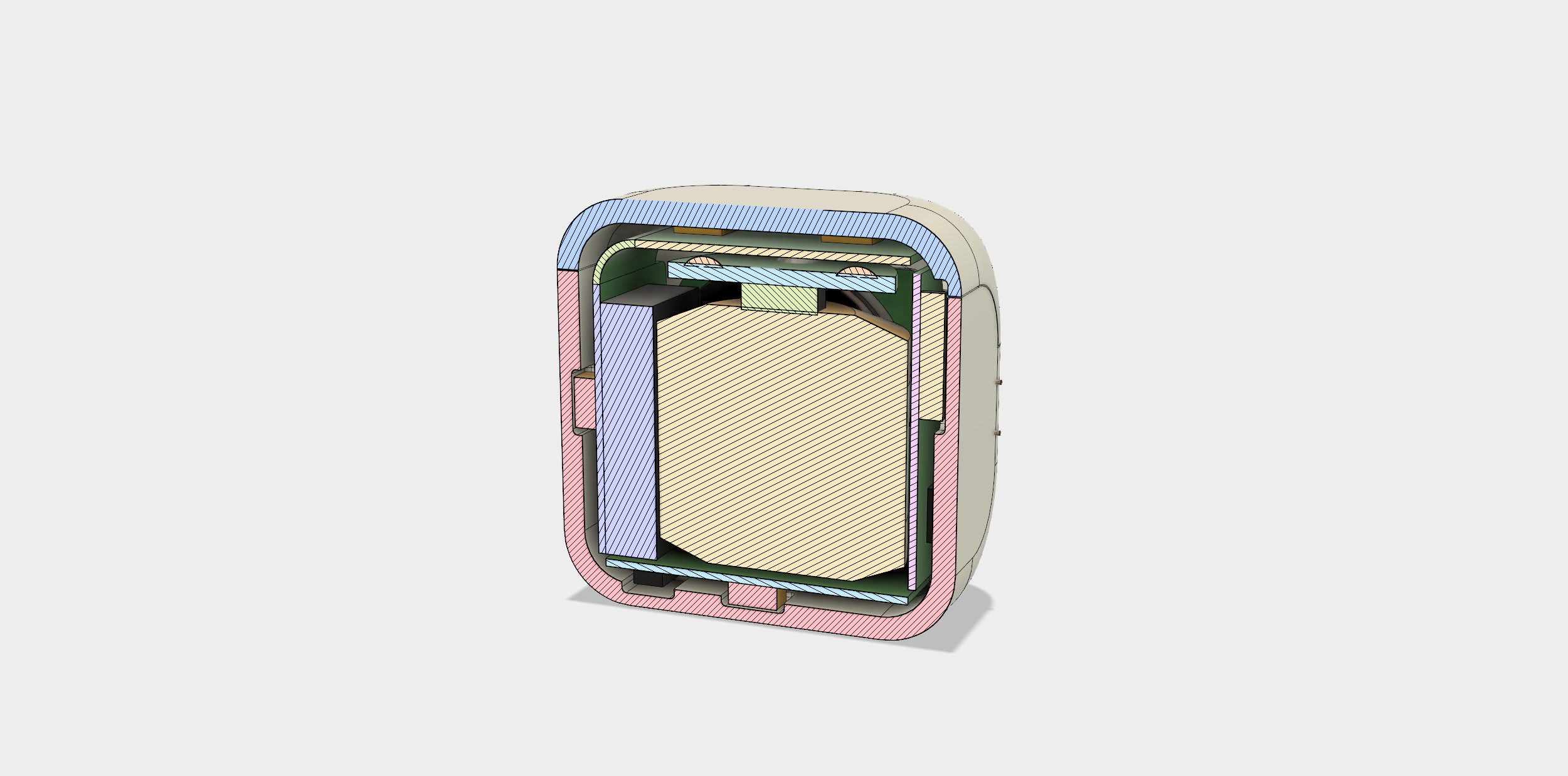
This here is a 60mAh battery. It is smaller than my previous 1/3N non rechargeable one, but with a slightly higher voltage (3.7v instead of 3v). In the end, I will be losing some capacity, the battery is just smaller than the other, but having a rechargeable battery is totally worth it. Plus, because it is smaller, I can now make the die a standard size of 16mm, just like any other playing die. This is very exciting.
So as you can imagine, I couldn't resist getting started on the next version. And while I don't have the finished product to quite yet, I can show you what it will look like.
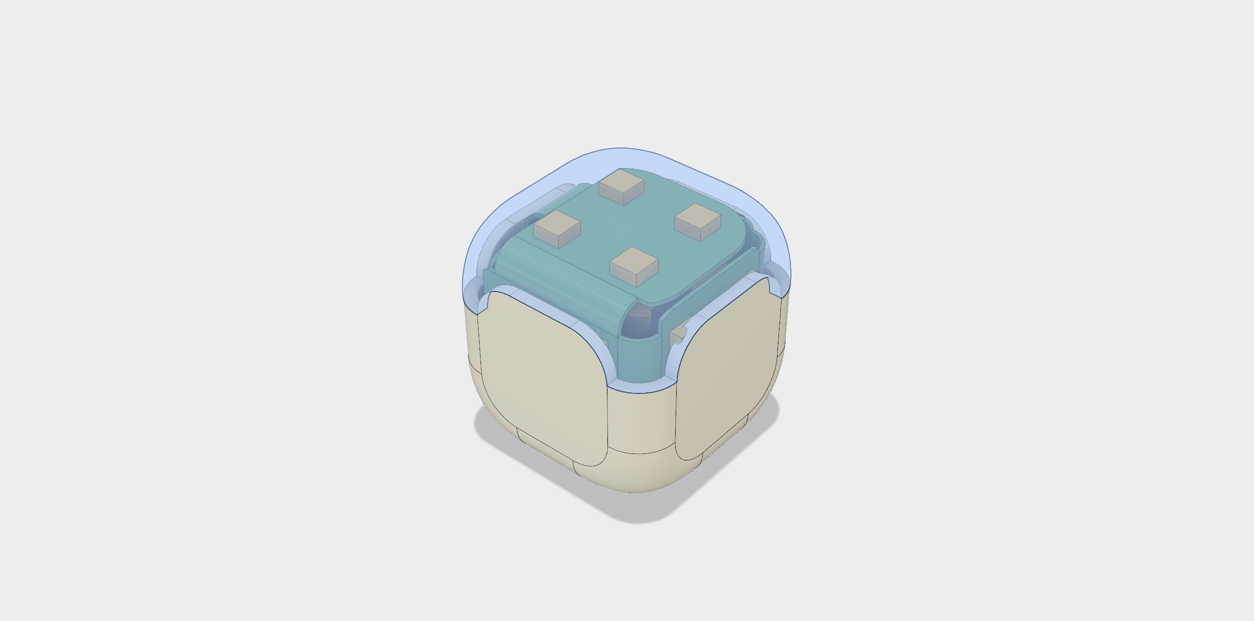
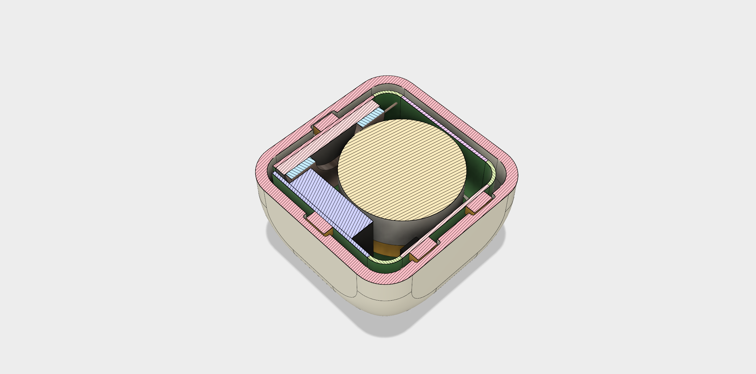
Fitting all the components inside the case was another level of Tetris mastery. The reduced size combined with the more aggressively rounded corners left me with very little room to fit everything. At this scale, even deciding where to put the folds is a major consideration, as a 1mm or 2mm bending radius will mean that that edge of the board can't be as long and there won't be as much room for components. In fact, fitting the Simblee chip on the board was almost impossible.
Then, of course, there are the APA102s. Because these are typically 5V devices, I wasn't sure if they would accept a 3.3v logic level. I knew they could be run on 3.7v, there is evidence of that all over websites like Adafruit, but I wasn't sure about 3.3v logic... In the end, I found out that they work just fine.
Wireless Charging Anyone?
I basically restarted the design of the case and board layout from scratch. I made the starting cube 16mm instead of 17, and rounded the corners a lot more than I had before. Keeping a wall thickness of 0.9mm gave me a new set of constraints for the interior of the die, especially in order to fit the LEDs on the outside. You see, the APA102s are pretty thick, comparatively speaking. This meant I HAD to cut out pockets for them on the inside of the case. Otherwise I wouldn't have been able to fit all the components on the board.
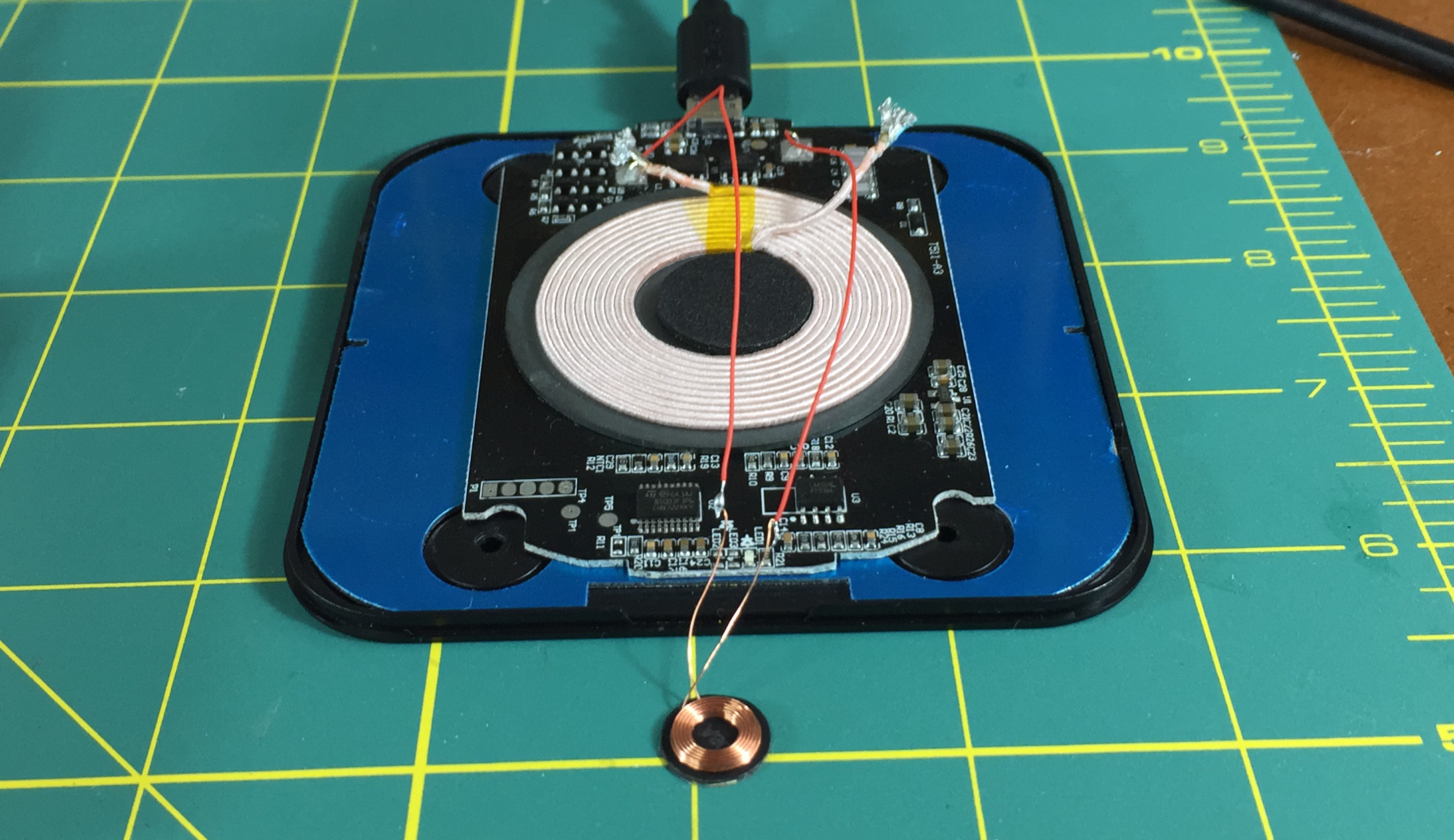
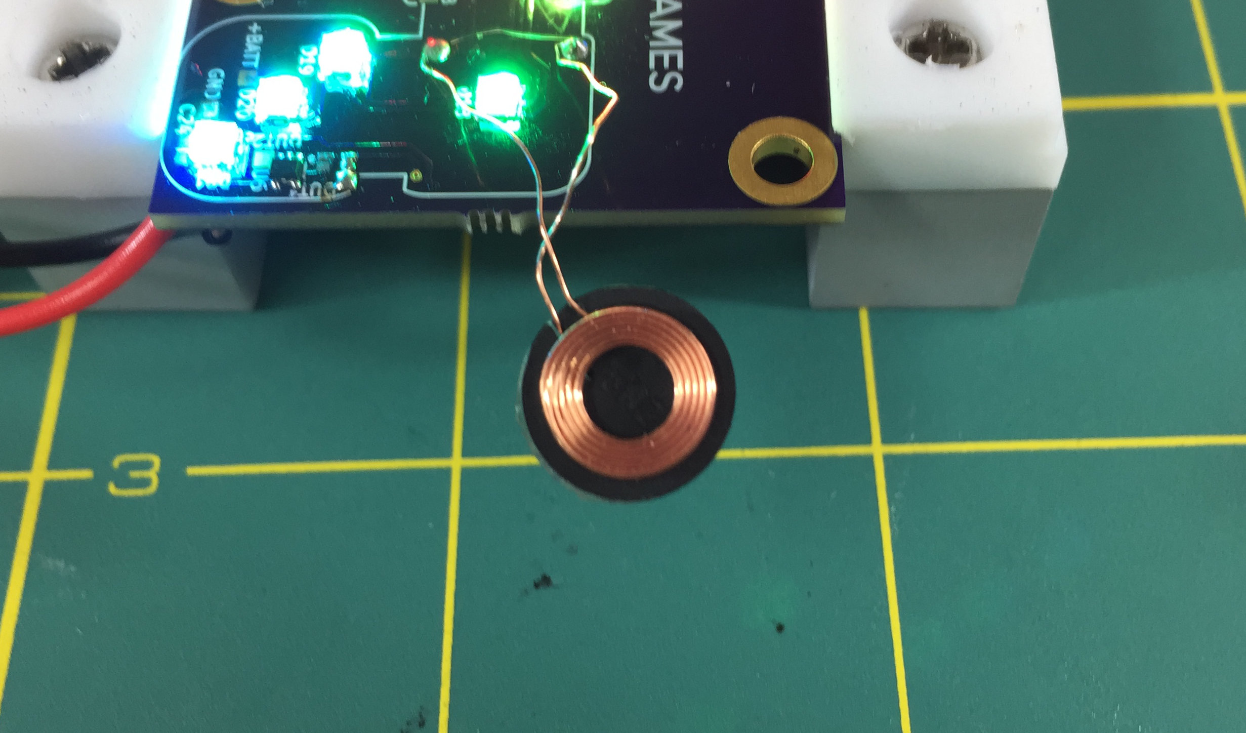
Having a rechargeable battery means needing to recharge it. I considered briefly using the metal screws holding the lid in in the previous version as charge terminals, but didn't really like the idea. So I decided to look into wireless charging, and as it turns out, not only is there a chip, from Texas Instrument, that will handle the wireless Qi standard AND charge a Lipo battery, but there are also wireless charging coils small enough to fit inside the die!
This was really great news, because if I can use wireless charging AND Over-the-air programming, then I never need to open the die again, which in turn means I don't need screws, or more importantly, the volume it takes to have something for them to screw into! I can just solder everything up, fold it inside the case, and glue the lid on.. I can even pot the entire insides with epoxy to make sure nothing shifts around and giving the die a more solid feel.
Prototype Board #2
Eventually I submitted a new prototype board to my favorite PCB house, Oshpark. The board came back, and I proceeded to try and assemble it by hand. It's funny, after you've soldered a bunch of 0402 resistors, a 0603 looks positively huge! :) I used a combination of techniques to do this, sometimes applying a bit of solder paste over all the pads, and then letting the solder flow to the chip pins as I heat it. It works surprisingly well.


